AnatolSher
AnatolSher - Сертифицированный эксперт
Lover of the ocean, yachts and Arduino

Зарегистрироваться на 1 年前

ответ
25
статьи
8
Наблюдатель
2

You don't need to do anything. Examine the code in the lv_port_disp. c file. When the USE_PSRAM parameter is enabled, memory for buffering is initialized in the lv_port_disp_init () function. You can play with the buffer size there

Hello newbie! When adapting code for STM32 to use on the W806, you need to understand the differences in the hardware of these controllers. That is, the code can be divided into two parts - hardware dependent and hardware independent. You must rework the hardware-dependent part in relation to the features of the W806.
You may not need STM32-specific header files

Compare your component installation with the W806 board circuit diagram. Maybe the USB-UART converter is not working
W801-KIT-V1. 0-schematic. pdf
HLK-W806-V1-0-KIT. png

@1201 If your calculations require a large amount of RAM, use PSRAM for your arrays and variables. Solder the chip on top of the w801 board. When outputting to UART, reduce the transmission block size.
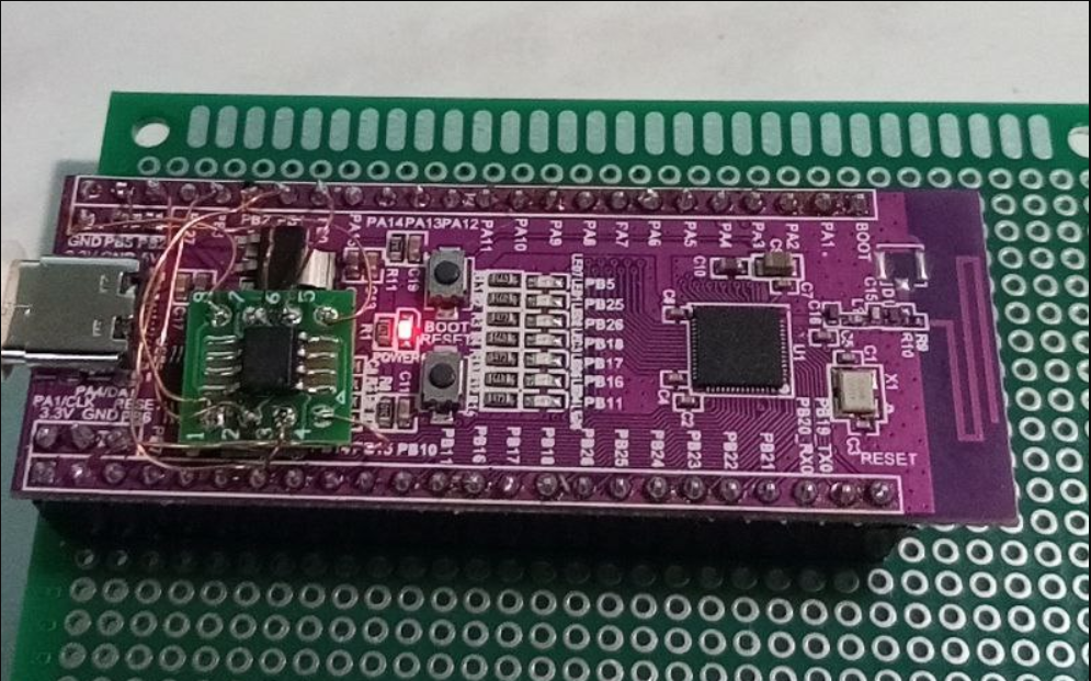
image. png

To help you we need to see the code. Show us how you use the EEPROM class

You can use this intermediate build. WiFi/BLE service classes are still under development but can be programmed in SDK style
Installation instructions here http: //ask. winnermicro. com/article/187. html
core_w80x. zip

Attention! I don't see what users write to me here. The last entry is Put build800. zip (unzip! )
If you cannot download the main package through the board manager, Try through the Chinese mirror http: //ask. winnermicro. com/article/172. html

For Linux w800build is not needed

Hello! I just checked the compatibility of our Arduino core with DHT series sensors. This works with the DHTStable library. This means that it can be ported to the W80X-SDK without much difficulty or look at the 1-wire interaction algorithm
image. png

Depends on the SDK you are using. In HAL 0. 6. 0 - HAL_Delay (1000) . In W80x-SDK you can pull the delay () function from iperf_timer. c
It usually works in microseconds. But delay maybe not less than 1 milliseconds. It will look like this for you

extern int delay (int us) ; 
//your code
int ms = 1000;  //1s = 1000 ms
delay (ms*1000) ;  // in uS
//your code

If you need to call a specific function every 1 second, you can use vApplicationTickHook or RTOS timers
For example
image. png
in vApplicationTickHook () you can creat a counter
Or create a separate RTOS task

Hello! Depends on the display board manufacturer. If you have such a display:
image. png
You can control the brightness via on/off or PWM. The main energy consumption goes to the display backlight. A lot of useful information can be found at https: //dronebotworkshop. com/gc9a01/

PS. In addition, any display controller has a sleep command. You can find it in the datasheet

Hello! To organize communication between several MCUs via UART, you need to look towards the MODBUS protocol. This means that the network has a master controller and many slaves. There are other options for many to many communication. Via CAN interface adapters and maybe Lin or K-line

Topology is: MODBUS
image. png
Or CAN
image. png
Or Lin
image. png

Very strange and incomprehensible circuitry.
Okay, at the ADC3 input you want to monitor the battery voltage. Maybe Li-Ion 3. 7 (4. 2 max) volts. Then the maximum battery voltage needs to be scaled to 2. 4 volts. Then the lower arm (R17) of the divider is about 270 kOhm.
What is VCC voltage? If 3. 3 volts, then the ADC4 input will have a voltage of about 2 volts if the sensor is not connected. The common connection point R18/C12/R14 is the summing point

Disconnect ADC3/ADC4 from your circuit and look at the ripple separately from the MCU inputs. There may be a problem with the controlled voltages. What is the frequency and amplitude of the pulsations?

I don't speak Chinese and may have misunderstood your question.

Hello from Russia : ) In addition to YUN expert's answer. . .

Each task of the FreeRTOS system uses its own, individual stack. If a task was created using the xTaskCreate () API function, then the stack memory is automatically allocated from the FreeRTOS heap, and the allocated stack size is determined by the parameter passed to xTaskCreate () . If a task is created by calling xTaskCreateStatic () , memory for the task stack is pre-allocated by the application developer. Stack overflow is the most common cause of application instability. Therefore, FreeRTOS provides 2 mechanisms that can be used to help identify and fix stack problems. The option used is configured by the constant configCHECK_FOR_STACK_OVERFLOW.

Please note that these options are only available on architectures where the memory card is not segmented. Also, some processors may throw an error or exception in response to stack corruption before the FreeRTOS kernel overflow check can occur. An application must provide a stack overflow hook function unless configCHECK_FOR_STACK_OVERFLOW is set to 0. The hook function must be named vApplicationStackOverflowHook () , and have the following prototype:

void vApplicationStackOverflowHook ( TaskHandle_t xTask, signed char *pcTaskName ) ;

Here the parameters xTask and pcTaskName pass the handle and name of the problematic task to the hook function, respectively. However, it should be noted that depending on the severity of the overflow, these parameters themselves may become corrupted, in which case the pxCurrentTCB variable can be inspected directly.

Stack overflow checking introduces additional context switching overhead, so it is recommended to use this check only during the testing phase.

[Stack Overflow Detection, Method 1]

It is likely that a task's stack will reach its greatest use (greatest depth) after the RTOS kernel brings the task out of the Running state, because at that point the task context (i. e. , the current running state of the task) must be on the stack ) . At this point, the RTOS kernel can verify that the processor's stack pointer remains within the valid stack area. The stack overflow hook function will be called when the stack pointer contains a value that exceeds the allowed stack space.

This method is fast, but it is not guaranteed to catch all stack overflows. To use this method only, set configCHECK_FOR_STACK_OVERFLOW to 1.

[Stack Overflow Detection, Method 2]

When a task is created, its stack area is filled with a known value (usually byte 0xA5) . When a task exits the Running state (context switch) , the RTOS kernel can check the last 16 in valid stack space to see if they were overwritten by the task or an active interrupt. The stack overflow interception function will be called if these 16 are not in their original value.

This method is less efficient than method 1, but it is still quite fast. It is highly likely to catch stack overflows, but is not guaranteed to catch all overflows.

To use method 2 in combination with method 1, set configCHECK_FOR_STACK_OVERFLOW to 2. Method 2 cannot be used alone.

I hope this information will be useful
Very good explanation provided by my colleague:
https: //www. youtube. com/watch? v=ogaPlNG_jQo
Perhaps there is a way of simultaneous translation into Chinese

Hello. We are working on a FastLED compatibility issue with our Arduino core. You can try the intermediate version https: //github. com/board707/FastLED
Please report any issues here or on github

опубликова
вопросы