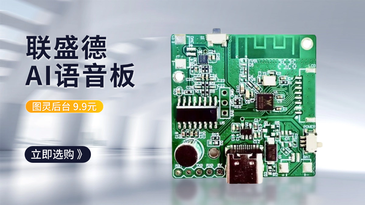
W801X Arduino 读取光敏传感器 AO 端口输出
发布于 2023-07-14 10: 48: 46
光敏传感器介绍
光敏传感器有两个输出, 一个是 DO (Digital Output) , 另一个是 AO (Analog Output) , DO 是数字输出, 只输出 0 或 1, AO 是模拟输出.
必需品
- 1 x 面包板
- 1 x W801 板
- 1 x 光敏电阻传感器模块
- 5 x 跳线
光敏传感器原理图

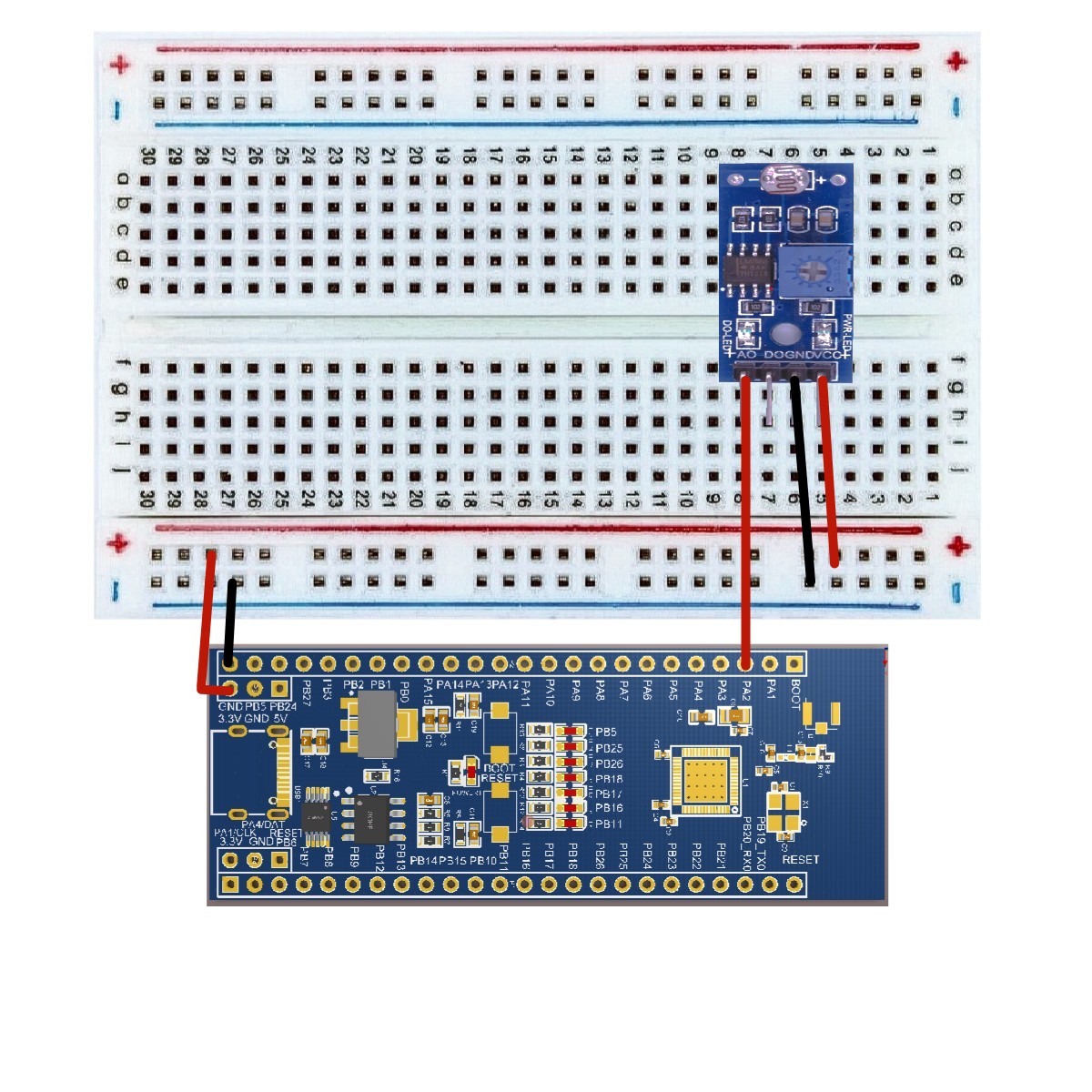
接线图
根据电路图连接面包板上的元件, 如下图所示.
草图
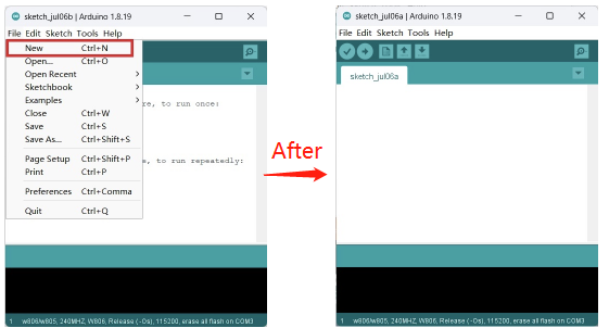
在计算机上打开 Arduino IDE 软件. 使用 Arduino 语言对电路进行编码和控制. 点击 "新建" 打开新建草图文件. 这里不讨论具体的配置.
代码
/*

 读取模拟电压
 读取引脚 PA2 上的模拟输入,  将其转换为电压,  并将结果打印到串行监视器.
 图形表示可使用串行绘图仪 (工具 串行绘图仪菜单) .
 将电位器的中心引脚连接到引脚 PA1,  外部引脚连接到+5V 和地.

*/

#include "Arduino. h"

void setup ()
{
  Serial. begin (115200) ;   // initialize serial communication at 115200 bits per second:
  pinMode (PA2, ANALOG_INPUT) ;   //Initialize PA2 port as the analog input port
}

void loop ()
{
  float volt = 0;
  volt = analogRead (PA2) ;
  Serial. printf ("ADC millivolt [%f]\r\n",  volt) ;
  delay  (100) ;
}
代码导入步骤
首先单击 Verify 验证代码是否正确

接着单击 Upload 上传代码弹出保存框, 在相应的位置编辑文件名并保存即可

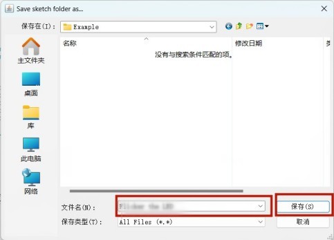
也可以如下步骤
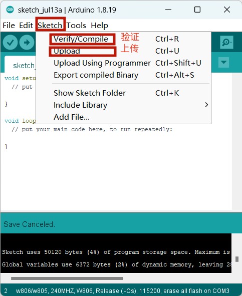
最后等待上传需要十几秒的时间, 显示以下即表示成功

代码解释
你在设置功能中做的第一件事是使用以下代码以每秒 115200 比特的速度启动板和计算机之间的串行通信:
Serial. begin (115200) ; 在代码的主循环中, 您需要创建一个变量来存储来自光电传感器的电压值.
volt = analogRead (PA2) ; 最后, 您需要将此信息打印到串行窗口. 你可以在代码的最后一行使用 Serial. printf () 命令:
Serial. printf () ; 现在, 通过单击顶部绿色条右侧的图标或按 Ctrl+Shift+M, 在 Arduino IDE 中打开串口监视器. 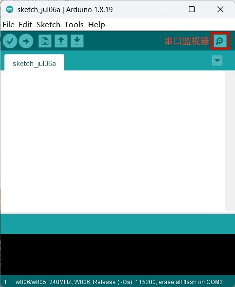
结果
你会看到一个从 0. 0 到 2. 5 之间的稳定数字流. 当你遮挡光敏电阻时, 这些值会改变, 对应于引脚 PA2 上的电压.
0 条评论

